


Magnetometer Data: Hardware
Magnetometer data is delivered to the Australian Space Forecast Center (ASFC) at SWS Sydney from SWS field sites (Figure 1), joint installations between SWS and other organisations, and directly from other organisations. The list of stations indicates the organisations responsible for the various combinations of sensor and data acquisition systems for the associated data streams received by the ASFC. The information below pertains to SWS hardware only.

Figure 1: A schematic representation of the SWS data NETwork showing the different types of data received from the various stations. Antarctic stations are maintained by the Australian Government Antarctic Division (AGAD).
An SWS field station may host several different systems for measuring various aspects of the space weather environment, typically a combination of some of the following: ionosondes, radio spectrographs, solar telescopes, HF radio monitors, TEC (Total Electron Content) monitors, magnetometers, and other space weather monitoring equipment installed in collaboration with other organisations. The SWS MAGnetometer system (IPSMAG) comprises the magnetometer sensor and enclosure, power supply, data cables, data acquisition equipment, logging software, timing equipment, LAN, and communications computer (COMMS PC). The earliest systems deployed are referred to as IPSMAG v1.x with the more recent systems deployed referred to as IPSMAG v2.x. The information below provides details on the different components of the magnetometer system.
Sensor and enclosure
IPSMAG v1.x
The IPSMAG v1.x magnetometer (Figure 2) was designed and constructed by Microscan Electronics, South Australia, to specification and incorporates a Bartington three-axis fluxgate sensor (Figure 3). The sensor and electronics (Figure 4) are sealed in a PVC pipe housing of length 700mm and 60mm diameter for installation in the field.

Figure 2: Photo of one of the IPSMAG v1.x magnetometers designed and built by Microscan Electronics Pty Ltd (a 30 cm ruler provides a scale for dimension comparison). The sensor and electronics are inside the yellow PVC pipe housing (see Figure 4).
Multi-core shielded data cable exits through a sealed gland and carries the magnetic field measurements as voltage signals back to the data logging system in the SWS building. The cable also provides power to the magnetometer from a CONDOR DC low noise power supply unit (Figure 5) located in the SWS building. The sealed magnetometer is buried with sand in a large waterproof cylinder enclosure of 600mm diameter and 1.5m in length, of which approximately 1.2m is below ground level (Figure 6). This provides some temperature stability. The four IPSMAG v1.x sensors were labeled VM1-VM4 respectively and were calibrated using facilities at Geoscience Australia. The calibration parameters for the IPSMAG v1.x magnetometers are as follows.

Figure 3: Bartington 3-axis fluxgate sensor contained within the IPSMAG v1.x magnetometer.

Figure 4: Photo showing Bartington sensor and electronics of the IPSMAG v1.x magnetometer which are sealed within the PVC pipe for installation in the field.
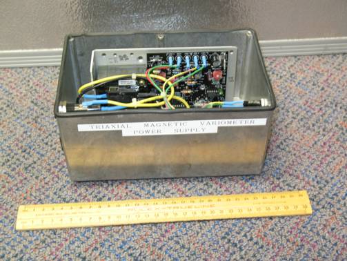
Figure 5: CONDOR DC low noise power supply (model HTAA-16W-A+) used to power IPSMAG v1.x magnetometer unit.

Figure 6: Photo of IPSMAG v1.x magnetometer enclosure. This enclosure is a sealed cylinder of approximately 600mm diameter and 1.5m in length, of which approximately 1.2m is below ground.
IPSMAG v2.x
The IPSMAG v2.x magnetometer is a three-axis MAG-03 Bartington Fluxgate Magnetometer (Figure 3) mounted on a magnetometer turntable (PDF) base (Figure 7 and Figure 8) that measures the absolute values of the geomagnetic field in three components. The turntable base of IPSMAG v2.x allows for more accurate aligning and leveling of the sensor. Multi-core shielded data cable carries the magnetometer signals to the recording equipment in the station building as well as providing power from the MAG-03 Bartington Power Supply Unit (Figure 9) to the sensor in the station magnetometer enclosure (Figure 10). The IPSMAG v2.x enclosures were either above ground structures (Figure 11) or IPSMAG v1.x enclosures adapted for the IPSMAG v2.x sensor (Figure 12).
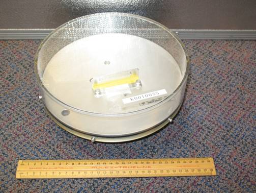
Figure 7:Photo showing turntable (from above) used for mounting the Bartington MAG-03 magnetometer unit for IPSMAG v2.x.
The calibration certificates (PDF files) for the IPSMAG v2.x sensors are as follows.
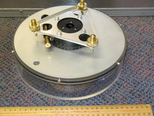
Figure 8: Photo showing turntable (from below) used for mounting the Bartington MAG-03 magnetometer unit for IPSMAG v2.x.
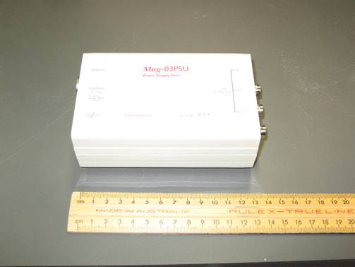
Figure 9: Photo of Bartington power supply unit for MAG-03 sensor used in IPSMAG v2.x.

Figure 10: Photo of IPSMAG v2.x magnetometer showing sensor mounted on turntable in enclosure with multi-core data cable providing power to sensor and returning voltage signals to SWS building.

Figure 11: An IPSMAG v2.x enclosure.

Figure 12: An IPSMAG v1.x enclosure adapted for the IPSMAG v2.x sensor.
Recording equipment
The recording equipment flow chart shows the general form used for both versions of IPSMAG which comprises a dedicated control PC (Windows O/S) as part of LAN, a junction box for the magnetometer signal, an A/D-card and associated software, GPS timing equipment and associated software, and an Ethernet card. Analogue voltage signals from the magnetometer are connected to the A/D-card installed in the PC through the signal junction box. Graphical interface software is used to configure the A/D-card driver software for digitizing the analogue signal and writing the data samples and time stamps to files. Timing accuracy is provided by synchronizing the PC to GPS time. Data files are written to the communications computer (COMMS) using LAN over Ethernet. Details of the recording equipment and software used for IPSMAG versions 1 and 2 are given below.
IPSMAG v1.x
The control PC uses a Windows 3.11 (or DOS) operating system and a National Instruments A/D-card, either the PC-LPM-16 (16-channel, 12-bit A/D which is no longer available) or the PC-516 (PDF) (8-channel, 16-bit A/D). The signal junction box (Figure 13) provides voltages from (and power to) the magnetometer to the analogue inputs of the A/D-card via the BNC connectors and an additional A/D junction box with BNC inputs and ribbon cable to the A/D-card (pin-outs given in the PC-516 (PDF) data sheet). The software drivers for the A/D-cards are given in the NI-DAQ library. The A/D-cards are initially configured using National Instruments Measurement and Automation Explorer(MAX)software. A graphical user interface (GUI) for data logging, data display and further configuring of A/D-card parameters (eg, sample frequency, analogue input channels, data filenames, device number) was developed "in-house". The application was called "Record" and employs the NI-DAQ driver software, with version 1.0 for the PC-LPM-16 A/D-card and version 1.1 for either the PC-LPM-16 or PC-516 A/D-cards.
The PC time was maintained to within several milliseconds of GPS time using a Masterclock system. This system comprises an active GPS antenna system (PDF), a GPS time code generator (GPS-100 or GPS-200 (PDF)), and a time code reader card installed into the PC (TCR-200 or TCR-500 (PDF)). Driver software corrects the PC time to GPS time (to within several milliseconds) every 30 seconds.

Figure 13: Signal junction box of IPSMAG v1.x system. The magnetometer voltages are connected from the BNC connectors to an additional junction box with BNC connector inputs and a ribbon cable to the A/D-card PC-516 data sheet.
IPSMAG v2.x
The control PC uses Windows 98 or higher, depending on the version number, and a National Instruments 24-bit A/D-card (NI-4351). The signal junction box is a National Instruments CA-1000 enclosure (Figure 14) containing a National Instruments connector block CB-68T (Figure 15) with on-board temperature sensors for compensating thermocouple temperature measurements (temperature measurements were used in IPSMAG v2.3.1 and higher). The software drivers for the NI-4351 A/D-card are given in the NI-DAQ library. The A/D-card is initially configured using National Instruments Measurement and Automation Explorer (MAX) software. A graphical user interface (GUI) for data logging, data display and further configuring of A/D-card parameters (eg, sample frequency, analogue input channels, data filenames, device number) was developed using the National Instruments Labview software. The different versions of the data logging applications are described below:

Figure 14: National Instruments CA-1000 enclosure used to connect BNC analogue inputs and thermocouple sensors to the NI-4351 A/D-card.
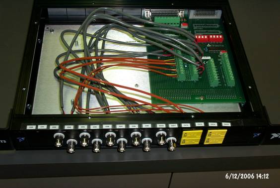
Figure 15: National Instruments connector block CB-68T installed into the CA-1000 enclosure. The CB-68T has an on-board temperature sensor for compensating thermocouple temperature measurements.
IPSMAG v2.0 employed a data logging application called VirtualBench (PDF) which has been developed by National Instruments. The application appears as in Figure 16 and was used under Window 98. The application had limited configuration capabilities and required manual intervention after a PC reboot. This situation was not practical for installation at remote field station locations and an application to address these issues was required.
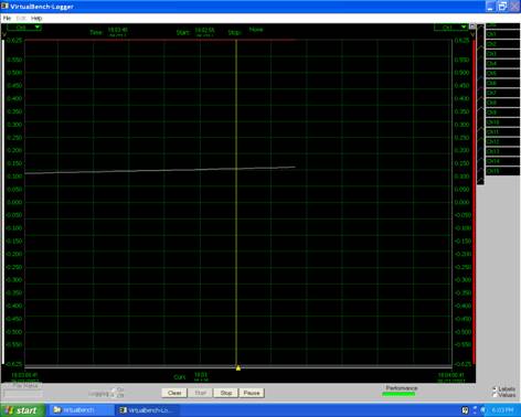
Figure 16: A screen capture showing the National Instruments Virtual Bench application used to acquire data from the NI-4351 A/D-card.
IPSMAG v2.1 was the first attempt to develop a configurable data acquisition application written in the National Instruments Labview environment in-house. The application was called Maglogger and appears as in Figure 17. Maglogger was developed and tested by a "summer vacation" student. This application was installed at the Camden field station, NSW, and found to have serious errors.
Note: Data from this application is not to be used.

Figure 17: A screen capture of the Maglogger application used to acquire data from the NI-4351 A/D-card.
Note: Data from this application is not to be used.
IPSMAG v2.2 again employed the data acquisition application VirtualBench (PDF) developed by National Instruments following the serious errors detected in the IPSMAG v2.1 acquisition software. The version number was incremented as the PC time reference for this version of the acquisition system was changed from that in IPSMAG v2.0 (see below).
IPSMAG v2.3 was a data acquisition application written in-house using the National Instruments Labview environment. The application was called Record and appears as in Figure 18. The block diagram of the main Record program (referred to as "VIs" in the Labview environment) is shown in Figure 19. The Record application could be configured (Figure 20) to re-start automatically after a PC reboot, as well as change many of the NI-4351 A/D-card configurable parameters.

Figure 18: A screen capture of the Record application used to acquire data from the NI-4351 A/D-card.
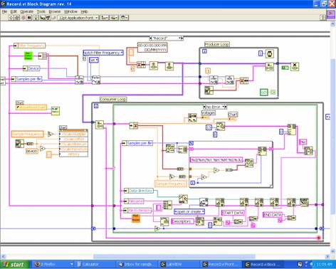
Figure 19: A screen capture of the block diagram of the main Record application "VI".

Figure 20: A screen capture of the Record application "sub-VI" used to configure NI-4351 A/D-card parameters, referred to as "EditConfig.vi".
For IPSMAG v2.0-2.1, the PC time was maintained to within several milliseconds of GPS time using a Masterclock system (refer Recording Equipment IPSMAG v1.x). For IPSMAG v2.2 and higher, the PC time was maintained to the within several milliseconds by standard Network Time Protocol (NTP) software referenced to the COMMS PC. For IPSMAG v2.2, the COMMS PC time source was referenced from SWS, Sydney. For IPSMAG v2.3 and higher, the COMMS PC time source was either referenced from SWS, Sydney, or a local GPS time source, as indicated in the timing logfiles of the station monthly archive CD's.
Communications computer
The magnetometer acquisition control PC was connected into the LAN using Ethernet.
Data transfer to ASFC
Data is transferred from the COMMS PC to the SWS file system on a routine basis. Incoming data streams are monitored in real-time and then converted into indices and plots for routine service delivery.
